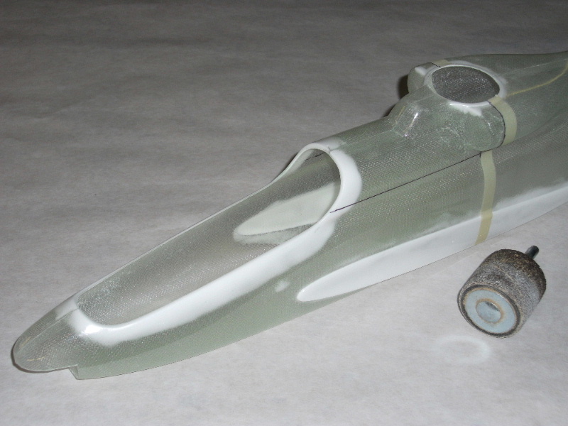
First up, mark and carefully cut out the opening for the main shaft and swash plate. With the opening completed and sanded, the access hatch is marked with a Sharpie pen. On my Cheyenne I opted for the smallest possible hatch, and while this looks very nice, it does make installing and removing the mechanics a very tight squeeze. The larger alternative hatch shown on the plans will make access easier and is required if you use the stock 150T main gear. The larger hatch can also make canopy installation easier.
The hatch is very carefully cut free. Use a thin razor saw, tape a metal straightedge in place as a guide, and take your time!
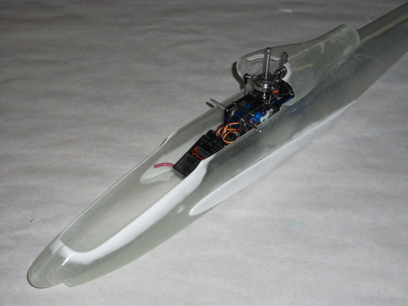
The mechanics slip neatly into place. The sponsons that house the retracts will stiffen the forward fuselage dramatically.
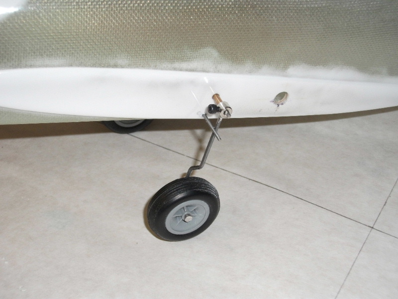
The retractable landing gear simply pivot on an axle which is supported by the 1/16" ply doublers beneath the 1/8" bearers for the mechanics.
Make sure the pivot for the landing gear is positioned far enough back so that it doesn't interfere with the motor.
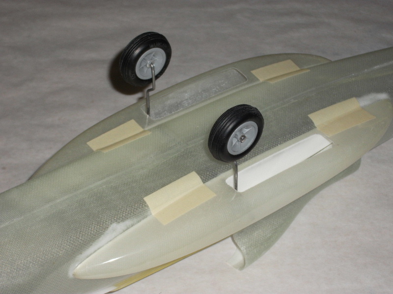
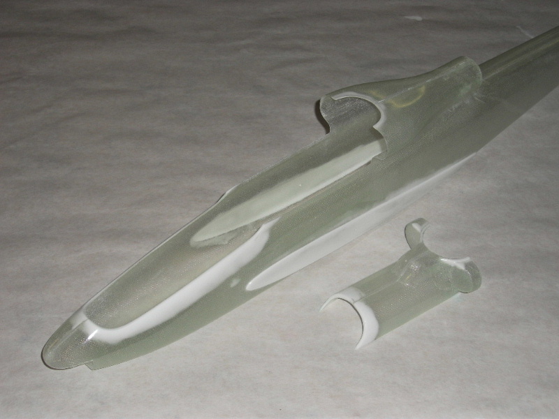
With the retract installation complete the sponsons can be test installed. Note: The sponsons should not be glued in place until the wing joiner sockets are installed (see below).
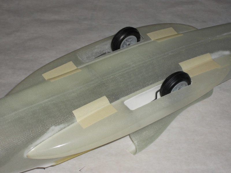
The retracts fold neatly back into the wells. The wheels are partially exposed just as on the full-scale Cheyenne.
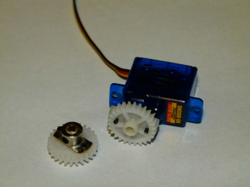
The retracts are actuated by a metal gear micro servo. I used scrap tail drive gears, as they were light and compact and strong enough for the application.
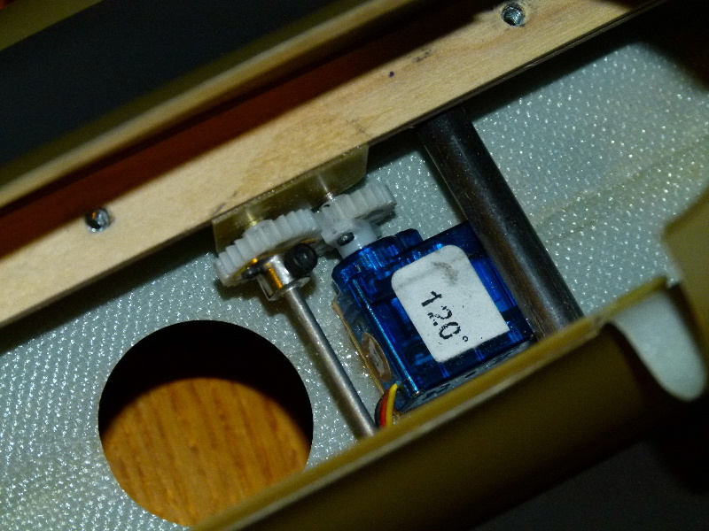
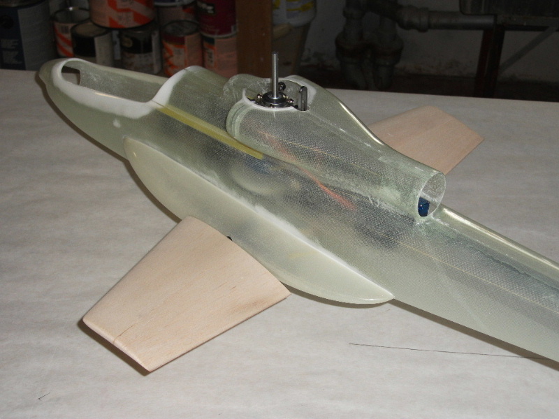
Here's the retract servo installed. Note that the 1/32 G10 plate supports the servo's output shaft. This simple mechanism has worked perfectly.
In this view you can also see the clearance/cooling hole for the Scorpion HK-2221-12 motor.
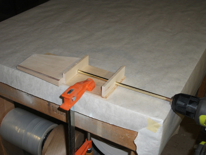
I made this jig to drill the holes for the carbon fiber wing joiners. In truth, you could also install them by simply cutting slots in the wings, epoxying the joiners in place and then filling the slots with scrap balsa. Just be careful to get the dihedral angle and alignment correct.
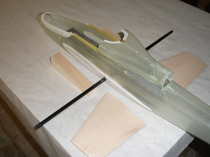
Here the female wing joiner socket is being installed in the fuselage. Be careful to get the socket absolutely horizontal and square. I recommend leaving the over-length socket free to slide back and forth. This will make it easier to cut the holes in the sponsons in the exact right spot. Once the sponsons are installed the socket can be trimmed to length and glued in place.
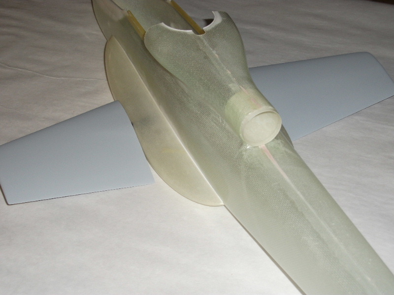
Here the wings are fitted into place. Use 1/16" music wire for the anti-rotation pins near the leading edges. I also drilled through the joiners inside the wheel wells and installed 1/32" music wire retainer pins. This locks the wings in place, but allows quick removal for travel.
I recommend glassing the wings with 0.56 ounce fiberglass and finishing epoxy. Then, after applying clear tape to the sponsons as a release liner, the wing roots are molded with Bondo. After the Bondo partially cures the wings are popped free and the Bondo is block sanded flush with the wing surface. The result is a perfect joint.
Note that the exhaust pipe has been formed from a strip of paper saturated with finishing resin. The strip is rolled up tight, slipped into place and then expanded to be a tight fit. The excess is trimmed flush after the resin cures.
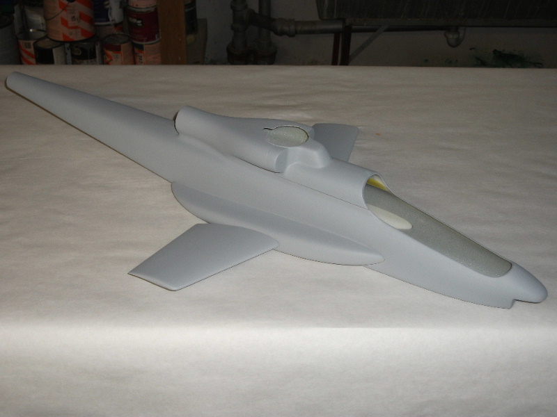
We're nearly there! The fuselage has received a final coat of primer preparatory to painting.