CH-47
Mechanics
Notes
The following notes
and photos are intended to provide additional tips and guidance for
those building this project.
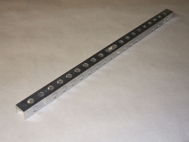
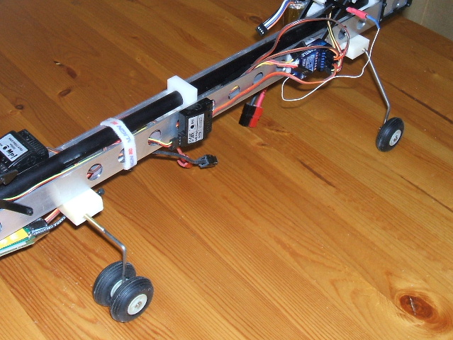
1. Main Truss: The truss is the backbone of the
helicopter. I machined mine from 1" square aluminum tube from the
hardware store, but you could just as easily build it up from plywood
or G10 fiberglass. The torsional loads are
actually pretty light, so my truss is certainly stronger than
necessary. Note the lightening holes and the slot in the middle
that allows me to route the wiring around the middle drive shaft
support block.
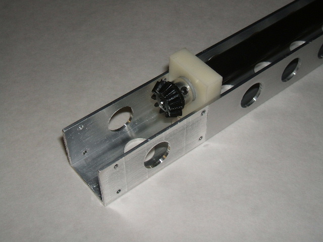
2. Drive Shaft and Bevel Gears:
Here's a closeup of the drive shaft, showing the bevel gear and
the journal block that supports the shaft housing. The bevel
gears mate with the crown gears on the rotor shafts to synchronize the
front and aft rotors. I used spare parts from the
widely-available Lite Machines Corona 120 for the drive shaft, but you
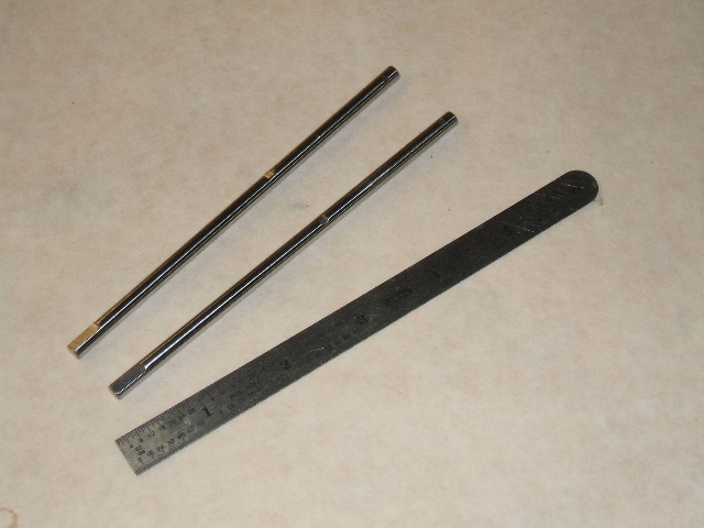
can use any suitable industrial bevel gears. Note that I used
5/64" (.078") music wire for the drive shaft, so the Corona bevel gears
and shaft bushings had to be reamed out to fit. I milled
the journal blocks from ABS barstock, but you could just as
easily cut them from plywood.
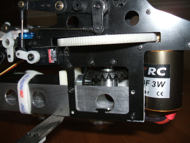
4. Heli Mechanics: The
main frames for the two mechanical mix helis are mounted to either end
of the truss. Note that the crown gears on the longer rotor
shafts mesh with the bevel gears on the drive shaft. The spurgear
and one-way bearing are removed from the aft heli while it's being
disassembled and reversed. The pitch input is disabled by
screwing that pushrod to a rigid post the same height as a servo (I
used a spare servo arm screwed to the side frame).
4. Landing Gear: The landing
gear are fabricated from music wire, brass tubing and wheel collars,
silver-soldered together. I installed the gear struts in blocks
milled from ABS barstock, but you could use plywood or solder them to
mounting plates. Note that the longer aft landing gear impart the
6.5 degree tilt of the main truss.
Mixer Programming: Click here to
download a word document describing how to set up the custom
mixers.